
Over the past Christmas and New Year’s holidays I finished my latest hobby project: a DIY electronic clock. “A clock? Big deal” you might think, but this one is a bit special, it was quite some work to get it finished and working, and I am pretty proud of the end result.
It all began rather disappointing…
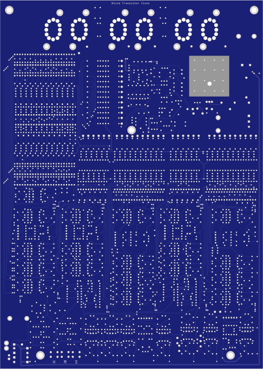
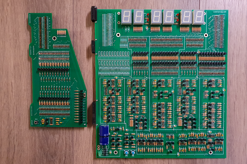
Three years ago, I stumbled online upon a DIY soldering kit of a “Transistor Nixie Clock” by KABtronics. This looked interesting, not only fun but also very educational to build. Nixie tubes have always fascinated me, so that was a big bonus. The clock could be build on a single, large, circuit board, and besides the nixie tubes is only made up out of four basic electronic components: transistors, resistors, diodes and capacitors. A lot of them, almost three thousand. No modern IC’s (Integrated Circuits) or even an oscillating crystal for time keeping (see the right column). The result would be a massive display of nicely arranged components, crowned with bright glowing nixie tubes, like a work of art. Gorgeous!
Unfortunately, they wouldn’t sell one to me.
This was the first disappointment. I doubt this was personal, but I never got a clear answer. Their website looks rather dated and unmaintained, they appear to be still in business but the nixie clock kit is probably long out of stock. Or they stopped selling them altogether due to liabilities. Although the rest of the circuitry is powered by an unharmful 12 Volts, nixie tubes require 180 Volts which can be lethal, especially on a totally unshielded circuit board.
LED display
So…I opted for the next best thing: a similar kit with the nixie tubes replaced with (less harmful) LED digits. And in the mean time contemplating ways to build the transistor nixie clock anyway, from own sourced parts and circuit board. At least the “Transistor Clock” kit (without the word “Nixie” in between) was available for sale. It was not cheap, and the local Customs office made it even more “interesting”, but it arrived in good order, in due time.
Cue the second disappointment. I was of course aware that this was an American kit, and Americans have different ways of doing things. For a start: their power grid runs not only at 110 Volts, but also at 60Hz. Not the 50Hz where I live. This is important, for a reason I will come back to in a moment. The “nixie kit” had the option to build it either for 50Hz or 60Hz, but the kit I got didn’t. This could be overcome however as there were already instructions online how to convert it to 50Hz.

The second problem was more serious though. Could the “nixie kit” be either build as a 12-hour clock or a 24-hour clock, the kit I now had was a 12-hour clock only. I hadn’t checked this before ordering, assuming it would have the same options as the “nixie kit”. I did not fancy spending a lot of time soldering and tinkering with a clock I had no use for and certainly wouldn’t hang on a wall.
All this resulted in two things: I put the kit aside “for sometime in the future”; and I started ordering the parts for the nixie clock and began thinking how I could acquire or reproduce the required circuit board. The parts I got quite fast, the circuit board became a whole different story and would become an on and off project by itself…
How does this clock keep time ?
The clock is powered by an AC-AC power supply. The public AC power grid has a fixed frequency (50Hz or 60Hz, that’s why it is called “Alternating Current”), with enough stability guaranteed by the power grid provider to be usable as a time keeping source. All the clock circuitry needs to do is convert this frequency to 1Hz (1 pulse per second) and use this as the basis for the clock digits counters.
This can be accomplished with the four basic electronic components mentioned above, but it needs a lot of them. They are build into the necessary flip-flops, logic gates and decoders. Building a kit like this really helps in learning and understanding the workings of these basic logic elements, and electronic circuits in general.
Time
Time, and clocks to measure and display it, we easily take for granted. For all of us time is a clock ticking forward at a steady unstoppable pace, a fabric of our existence. Yes, I know about relativity, other dimensions and what not, but that’s not the point. In our daily lives ‘time’ is as hard to describe what it really is as it is imaginable not being present. “Time…that’s seconds which make up minutes, and hours, and days, and so on when you add them up” is one way to describe it, but in the end humans have come up with the concept of ‘seconds’, so it is in a way artificial. It describes the passing of time, not ‘time’ itself… Time, of course, is not artificial.

Clocks and how they work
Clocks have been around for a long…time. By measuring the shadow of a stick in the ground as the sun moves across the sky, with an hourglass, or by mechanical masterpieces with gears and levers driven by gravity, springs or whatever human cleverness could come up with. Or with electronics. There are several ways an electronic device can tell time. You can measure a vibrating atom, which is a bit hard to do for most of us. You can also measure the time it takes for a capacitor to charge and trigger a transistor.
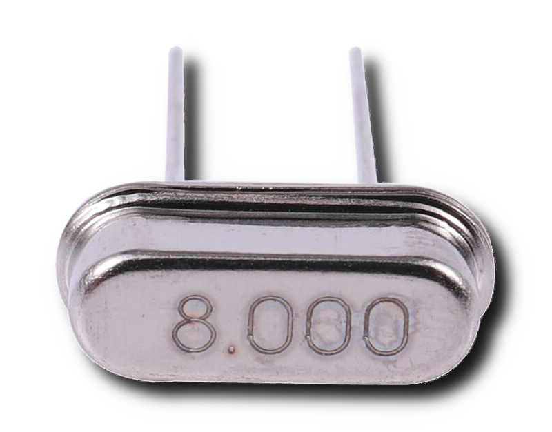
The most common way is by using quarts crystals which vibrate at a steady frequency (vibrations per time constant) when electrically aroused. Those crystals are in almost all electronic devices which use time in one way or another: computers, mobile phones, wrist watches, your dishwasher, toys…the list is endless. Micro-processors and -controllers need a clock to operate. Pry open any given electronic device and chances are high you will find a crystal in there. Of course it is very tiny and encapsulated, not a piece of bare quartz rock! But there is also another way, and that is exactly what the clock this post is all about does .
Let’s give it a go
Right after the disappointment of not being able to get my hands on the nixie clock, I started recreating he circuit board in Fritzing. Yes, I know KiCad is better, but for this project I only needed to draw the circuit board and for that I found Fritzing easier to use. However, that went nowhere. But last year I gave it yet another try, and this time with success (I think). At the same time, it sparked renewed interest in the clock kit I had still put away in the attic. Maybe…it could make it work, as a 24-hour clock?
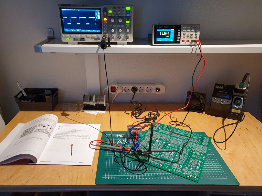
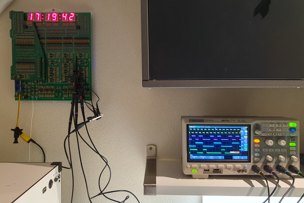
One of the fun parts of this kit is that it is build section by section, and you can see the working of each as you go along. In fact you must check each section if it works as it is supposed to, that could save you a lot of troubleshooting in the end when you power the complete clock on for the first time…and it is not showing the time. The functioning of each flip-flop circuitry can best be checked with an oscilloscope, but I found that a couple of LED’s (with a limiting 1K resistor) on a breadboard are very helpful (and satisfying to watch) too. Note that you need to connect the LED anode (+) to the 12V plus on the board, and the cathode (-) to a flip-flop line. As you progress down the bottom of the board, completing the so-called “pre-scaler”, the blinking of the LED(s) should become slower and slower after every step, until it blinks exactly once every second at the right side of the board.
With the pre-scaler working, it is time to start with the first, right-most, LED digit. Each of the six digits is driven by its own circuitry, quite independent from each other. So, basically, the only thing the right most seconds digit really does, is count from 0 to 9, changing every second with a pulse from the pre-scaler. When at 0 it also pulses the adjoining digit circuitry (the tens-of-seconds) to increment its counter.
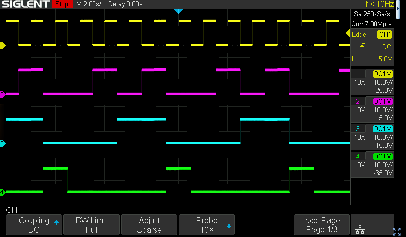
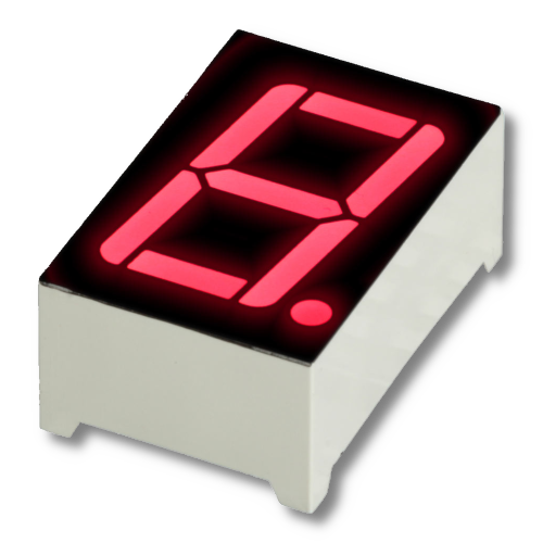
For the right-most digit, four flip-flops and two logical gates are enough to produce four unique on/off waveforms (and their inverses) which can be used in a truth-table to determine the value of the counter. Although all circuitry is analogue, the result is thus a 4-bit binary. Next comes the 4-to-10-line decoder, halfway up the board (still on the right-most column), which are ten AND gates build from (again) diodes, resistors and transistors. With this section working, we finally have ten output lines which (sequentially) become active every ten seconds, each for one second precisely. With a couple of LED cathodes connected to these output lines we can finally check that we have something working here which resembles a clock! All we need to do now is let the output lines drive the correct segments of a 7-segment LED display. For this decoder a whole array of yet more diodes are sufficient, plus some resistors to limit the current through the LED display. The result of all this labour is a single LED display nicely counting from 0 to 9 repeatedly.
The 24-hour clock
With growing confidence now that I had the first digit counting, and in the process learning more and more about how all those components and circuitry come together to make a working clock, I continued with the next three digits. Each are similar to the first one as described above, but not precise. The most obvious difference is that the tens-of seconds and tens-of minutes counters only count from 0 to 5. Also, to be able to set the time there is additional circuitry to manually advance the minutes and hours.
By this stage I had it pretty much worked out how I was going convert this 12-hour clock to a 24-hour device. Luckily, apart from the LED display driving circuitry versus that of a nixie tube, there are many similarities between the kit I was building and the nixie clock of which I had the full schematics and was in the process of reproducing in Fritzing. So…it should be possible to take the 24-hour circuitry of the latter and add it to my clock, no? For this I designed a new daughter circuit board, checked and double checked it (but still missed a couple of errors), and ordered my design from China.
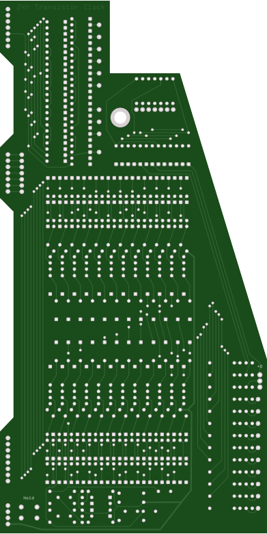
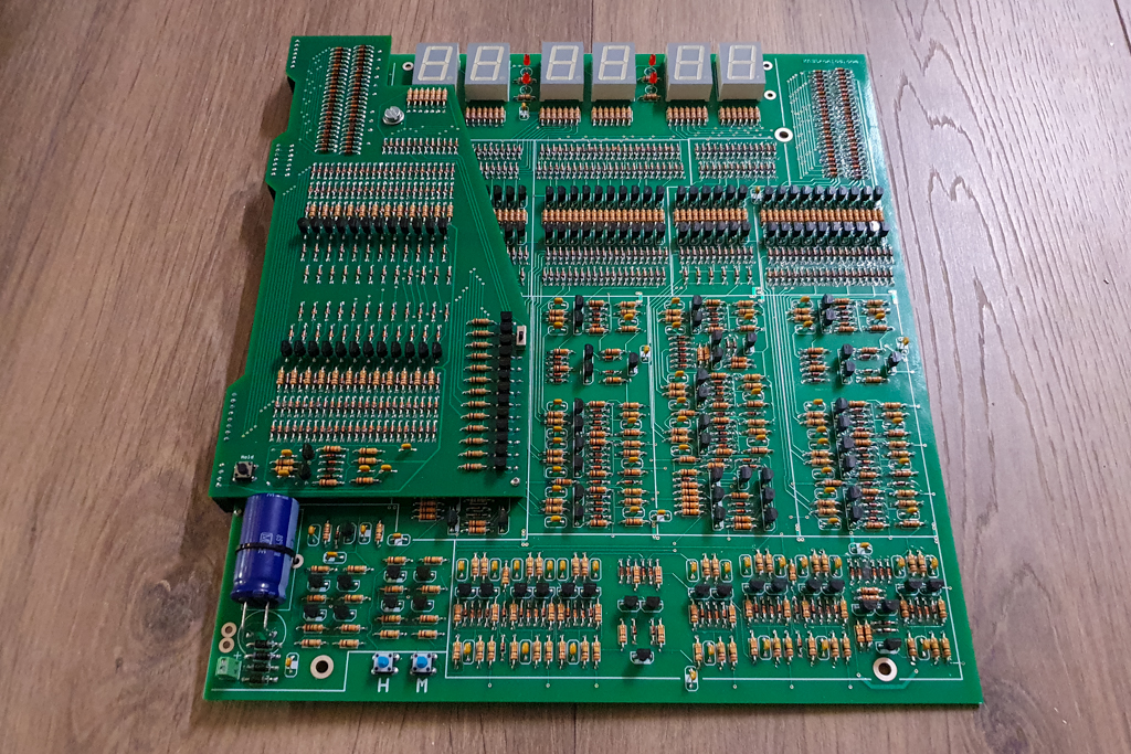
By itself it was a good exercise in designing a custom shaped circuit board, as I wanted to mount this board on top of the existing one but hiding the main board as little as possible. It also dawned to me that the main board was missing a button to freeze the clock counting, which is useful for setting the exact time as you can’t manually progress the seconds in the same manner as you can with the minutes and hours. So I added such a button to my board. And finally a switch to either show or hide the leading ‘0’ digit of the displaying hour. I needed a way to connect the two boards of course. At first I planned to just hardwire them together, but I figured it would be better to use male and female pin headers so they can be easily assembled and disassembled. I ‘just’ needed to design and 3D-print these connectors.
At the bottom of this daughter board is an additional flip-flop, which switches after 12 hours (at noon) so it is basically an AM/PM “switch”. The 4-to-10 line decoder are now two 4-12 line decoders (0 to 11 for AM, 12 to 23 for PM), with the AM/PM flip-flop selecting which is in use. Both hour display LED’s have their own 7-segment decoders, the hour decoder (0 to 9) is connected to the limiting resistors on the main board, but the tens-of-hours decoder (0 to 2) has the resistors on the new board because now all 7 segments of the leftmost LED display are used, instead of only 2 (displaying the number ‘1’) as on the original board.
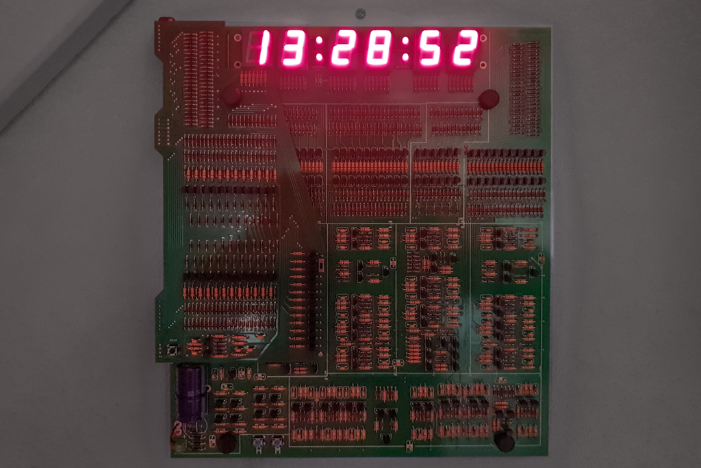
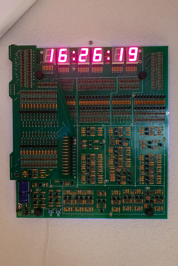
And here it is
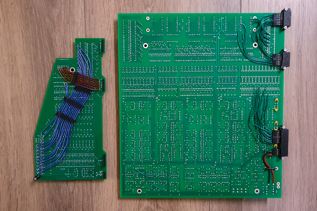
On the daughter board: The blue and brown wires connect the parts together, I choose this method to keep the size of the daughter board as small as possible. The leftmost two blue wires wouldn’t have been needed if I hadn’t made a mistake while designing the board. The same error also meant that I had to cut the traces to thirteen transistors and rewire them with small pieces of blank wire…
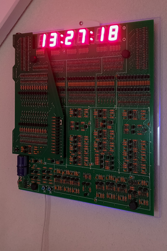
Will it work? Well…at first it didn’t, but fortunately I soon found the cause, or rather two: I had foolishly assumed the transistors on the nixie clock board had the same pin-out as on my daughter board, but that was (of course…) not the case. Secondly I had made a rather dumb tracing error when copying the decoder circuitry. Luckily both were easy to correct and after a short while the clock was running!
Initially I was a little bit worried if the hour circuitry flip-flops, driving the decoders through those connectors and longer lines, were not stable enough, but once mounted on the wall (and not touching it), it is all okay. I was already warned that the circuitry is very sensitive and a simple touch can easily have displays jump forward erratically. Which is fine with me, it adds to the character of the clock, I think. Just don’t touch.
Is it accurate ?
How precise is the 50Hz on the power grid anyway, can it keep time well enough to be any use as a clock?
The public power grid doesn’t actually maintain 50Hz frequency all the time, but it fluctuates a bit. The service provider however makes sure that the frequency is throttled up and down in a controlled way, so that over a period of time the average frequency is exactly 50Hz.
This clock is a great way to test this in practice. I have indeed found that over a long period, probably forever, the time is never more off than 30 seconds (too slow or too fast).
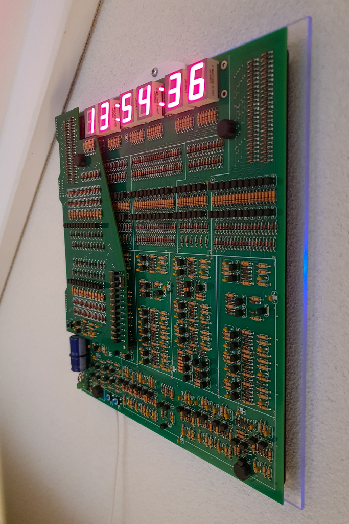
The finished clock was then mounted on a piece of acrylic sheet with 3D-printed mountings, nuts and bolts, For added effect a blue LED was mounted at the back of the main board (not on the photos shown above) and connected to the PM line of the AM/PM flip-flop, so the acrylic back plate is only illuminated during the afternoon and evening.
To be continued ?
This was a long but fun project! Even more so since I had no idea how and when this would end, if I would be able to convert the kit into a 24-hour clock at all. There were many hours of soldering involved, but because the kit is build per section, and you can check its proper working as you go along, it never got boring.
Sometime in the future, I will certainly give the nixie clock a try too. I already have all the parts, including the circuit board. So… more “timely” fun ahead!
Marco
Hi my name is Franco, I saw the modification you made to the transistorclock, I tried but without success. Could you help me?
Thanks
Hi Franco,
Which modification do you refer to, the 50Hz mod or the 24-hour clock (which is not trivial to do!). What did you try, and does the clock work without any modifications?
Hello Marco!
My name is Nándor Tóth
I made the 24H pcb panel you built based on your description, but it is not functional.
I probably did not design the PCB panel properly, and it was not properly connected with wires to the existing 12H hour panel, because it is not clear in the pictures you posted which wire connects to which.
The original transistor clock works, because I did not install the additional 24H panel due to malfunction, I installed the missing components on the original panel, and thus it is functional with a 12-hour display!
I would like to ask for help, because I would like to rebuild the 24H hour panel, for this I would need the SCH drawing of the additional panel, the panel PCB panel drawing (design – gerber file if possible), and how is the additional panel electrically connected to the original panel? The pictures you posted do not really show the connection of the wires on the panel.
Thank you in advance for your help!
Nandor Toth
Hi Nandor,
This blog post was never intended as a “how to”, so respect for the effort and trying! Sorry to hear it didn’t work in the end.
Anyway, I have now added the Gerbers and connection details to my Github:
https://github.com/Crouze/KABtronics_24h_clock_mod
Hopefully it will bring more success.
Marco
Dear Franco,
I have now added the Gerbers and connection details to my Github:
https://github.com/Crouze/KABtronics_24h_clock_mod
Hope this helps!
Marco
Hi Marco!
I am Nándor Tóth
I made the 24H pcb panel you built based on your description, I checked the description in the link you provided, and the gerber files, but it still doesn’t work – it doesn’t indicate 24-hour operation properly! the display jumps from 21:00 to 02:00, then counts normally to 08, then starts counting again and repeats from 01 to 08.
The original transistor clock works, because I still haven’t installed the additional 24H panel due to a malfunction, I installed the missing parts on the original panel, so the 12-hour display works!
I definitely need the SCH drawing and connection drawing of the 24-hour additional panel (definitely SCH) – I compared it with the gerber files you posted and the PCB panel I made. It’s the same, I didn’t find any errors in mine.
A question arose in my mind:
– In the picture “24h_board_bottom_1.jpg” you marked the soldering of a wire with the number “3” – basically the connection point of the Q95 collector, R19, which goes to the D522 diode (according to the original 12H circuit diagram) – and I don’t understand this, because you marked the same soldering point of the D522 diode with the number “17” in the picture “main_board_top.jpg” as a soldering point of a wire!
This wire is actually the “QJ_2” wire, which is actually connected to the 10kohm input resistor of the 24H panel Flip-Flop circuit with the soldering point “3”, and with the point “17” in the picture “24h_board_bottom_1.jpg”!
Is this correct???
Thank you in advance for your help!
Nandor Toth
Welcome!
Reading the additional panel design of the transistor clock, great design and implementation! I would greatly appreciate it if you could request the circuit diagram and the connection of the circuit to the original implementation. If you would make this available, I would send you the implementation of my plan based on them. Thank you in advance.
I had a board made but put it aside for a while. Recently however I have started on it and now have the seconds circuitry working with some LED’s. There are errors on the board, as I expected from a prototype, but none too bad, just a couple of traces. It will take time, this job needs to be done slowly, but once finished (and actually working!) I will share the gerbers (of the PCB with errors corrected).
Did you wind up getting the nixie board working? I was disappointed the original was discontinued as well– any chance you’d be able to share the layout for the custom PCB?